Tolerances & Clearances
Summarized below are the general clearance requirements and tolerance capabilities of our manufacturing and assembly processes. A selection of copper track widths for different copper weights are also given within.
Clearances
Clearance is the minimum distance required between two points on a PCB to avoid manufacturing, assembly, and general operational failures.
| Category | Starting Point | Target Point | Clearance |
|---|---|---|---|
| Test point | Test point | Test point | >=2mm |
| Test point | Frame edge | >=1mm | |
| Test point | Devices with a height greater than 2mm | >=3mm | |
| Test point | Location hole | >=3.2mm | |
| Holes | Screw hole or positioning hole | Device | >=1.5mm |
| FPC positioning hole | Pad | 2.2-2.5mm | |
| hole | hole | >=0.5mm | |
| RF | RF connector | Devices with a height greater than 2.5mm | >=4.1mm |
| RF connector | Fixture positioning hole | >=5mm | |
| RF connector | RF connector | >=11mm | |
| mark | mark point | Device | >=3mm |
| mark point | Frame edge | >=5mm | |
| Traces | Traces | Jigsaw connection point | >=1mm |
| Traces | Frame edge | >=5mm | |
| Device | Device | Device | Different for each device |
| Device | Golden finger | >=3.8mm | |
| Device | Label | >=1mm | |
| Device | Frame edge | >=3mm | |
| Device | Reflow soldering track edge | >=6mm | |
| Device | V-CUT line | >=1mm | |
| Device | Devices with a height greater than 9mm | >=6mm |
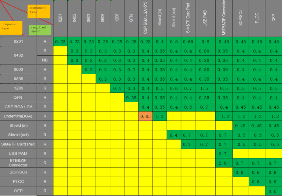
The component to component clearance are decided using the rules in the following table.

Tolerances
Tolerance is the machining accuracy attainable to produce each feature on a PCB.
The standard tolerance for PCB contours, slots, and cut-outs is ±0.15mm
Holes
Read more about Vias and Holes here
| Hole Type | Position Tolerance | Diameter Tolerance |
|---|---|---|
| NPTH | ±0.075mm | ±0.05 ~ ±0.075mm |
| PTH | ±0.075mm | ±0.05 ~ ±0.1mm |
| Vias | ±0.05mm | ±0.05mm |
Traces
| Trace Width | Tolerance |
|---|---|
| ≤10 mil | ±1.0 mil |
| >10 mil | ±1.5 mil |
Solder Mask
Solder mask should have an opening with a size bigger than 2 mils, and a bridge greater than 6 mils.
The characters to be printed as the silkscreen should have a character line width to character height ratio of 1:5. The commonly used character line sizes are
- 4/20mil,
- 5/25mil,
- and 6/30mil.
Track Width Choice
Inner Copper Weight
| Inner Copper Weight | Track width |
|---|---|
| 1/2OZ | 3/3mil |
| 1OZ | 3/4mil |
| 2OZ | 4/5.5mil |
| 3OZ | 5/8mil |
| 4OZ | 6/11mil |
| 5OZ | 7/14mil |
| 6OZ | 8/16mil |
| 7OZ | 9/19mil |
| 8OZ | 10/22mil |
| 9OZ | 11/25mil |
| 10OZ | 12/28mil |
Outer Copper Weight
| Outer Copper Weight | Track width |
|---|---|
| 1/3OZ base copper | 3.5/4mil |
| 1/2OZ base copper | 3.9/4.5mil |
| 1OZ base copper | 4.8/5.5mil |
| 1.43OZ base copper (positive film) | 4.5/7 |
| 1.43OZ base copper (negative film) | 44413 |
| 2OZ base copper | 6/8mil |
| 3OZ base copper | 6/12mil |
| 4OZ base copper | 7.5/15mil |
| 5OZ base copper | 9/18mil |
| 6OZ base copper | 10/21mil |
| 7OZ base copper | 11/25mil |
| 8OZ base copper | 12/29mil |
| 9OZ base copper | 13/33mil |
| 10OZ base copper | 14/38mil |
