PCB CAD Aperture File Types
Gerber
Gerber, is one of the earliest developed PCB CAD Aperture file type. Gerber has the lion's share of the market. The current existing EDA software and PCB manufacturing equipment support the use of this format. However, as the format is only maintained and promoted under the license of the company, this may set some limitations on commercial articles and patents.
History
1960: Gerber System Plotter Company develop the plot output format of the CAD software in the US. It was released in 1980 as A Subset of EIA RS-274-D Plot Data Format Reference Book, and gradually became the standard format.
1998: An extended version of the RS-274X Format User's Guide was released, which included an additional data block, the parameter block, and it's the more commonly used format today.
2014: The launching of the upgraded version of RS-274X with attribute information.
2019: The company submit a proposal for Gerber X3 that includes assembly information.
Data Format
- Control codes and coordinates: ASCII format, EBCDIC, EIA, or ISO codes.
- Aperture and parameter files: txt text files, art graphics files, DRL drill files, IPC test point reports, and other file types.
- Netlist and BOM table are independent to each other, so a separate chart needs to be defined to relate such information. Even the newest version of gerber has not met the backward compatibility requirements.
Given various file formats, Gerber needs to convert the intermediate data formats and verify the output configuration of EDA software to check if there is any difference from the configuration of production software.
These lead to the several shortcomings of the existing data format, i.e. the inherent limitations of the RS-274X Gerber format:
- A separate physical file is required for each layer of PCB information, such as manufacturing records and assembly layers, etc.
- Drill information (usually in the format of the N.C.drill file) needs to be sent separately.
- Layer stackup definition needs to be presented in the form of diagrams, text, or filenames and agreed upon with the manufacturer.
- The netlist used for testing (which contains the electrical connections between components) also needs to be sent separately.
- The pick-and-place file with component placement information and the BOM procurement file are also made separately, which often tends to cause errors.
IPC-2681
IPC-2681, also known as IPC-DPMX or Digital Product Model Exchange, is one of the "Application Characteristic Data" standards in the IPC 25XX Series of Data Exchange Standards of the IPC standards in the electronics industry. It is a new layered neutral data format with superior manufacturability, quality, reliability, and consistency for data information transmission between a PCB designer, a manufacturing and assembly facility. It is developed by a group of standards developers, tool developers, CAD users, and CAM users.
IPC-2581 is a late-comer to the party with the aim to solve the inherent problems with Gerber, which means it meets the needs of industrial IoT and data-based development better than Gerber. By promoting its affiliate membership program, IPC-2581 has become more widely known. However, the membership application needs to be done by all the upstream software and equipment vendors to downstream manufacturers, leading to some difficulties in real market applications.
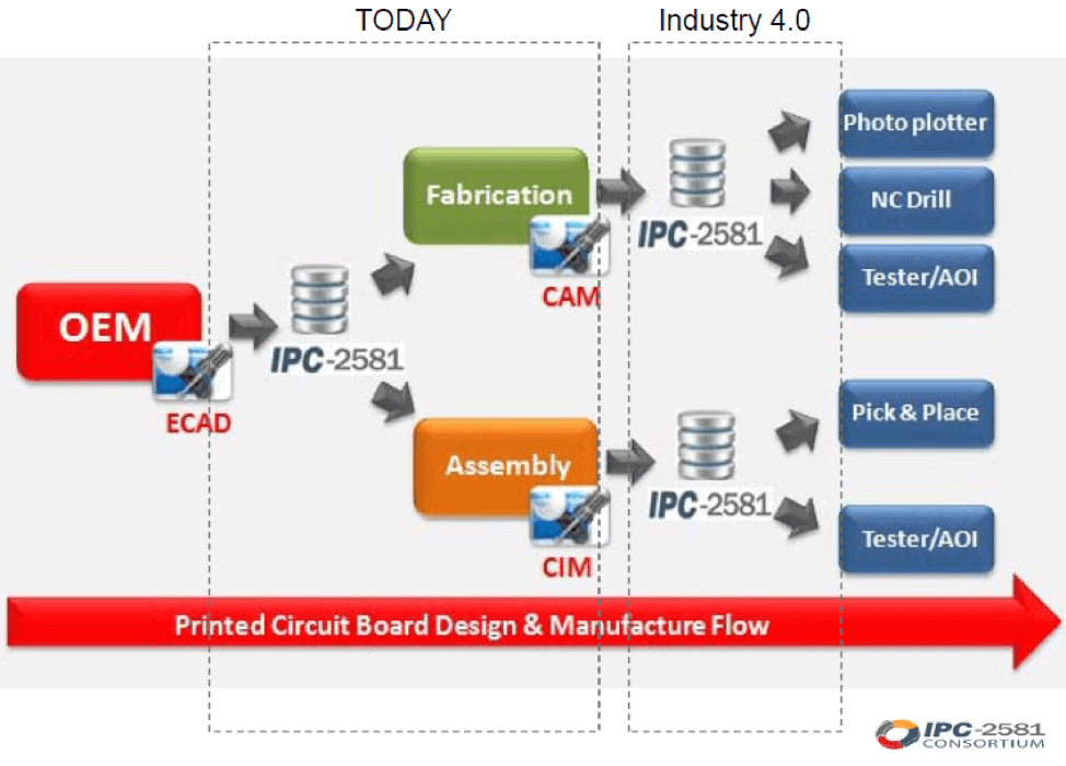
The standard is now being promoted by the IPC-2581 Consortium, with an independent website www.ipc2581.com. An updated version, the IPC-2581C, has been released in December 2020. The new version introduced even more groundbreaking new features.
History
1998: IPC issued GenCAM 1.0, a central product data standard.
2002: IPC issued GenCAM 2.0, also known as IPC-2511B, which is the first XML-based version.
2004: IPC developed and issued IPC-2581, which covers the previous content.
2013: IPC issued the IPC-2581B, adding features such as cascading switches.
2020: IPC issued the IPC-2581C, which includes bidirectional DFX data exchange.
Data Format
The IPC-2581 standard uses a single XML-based file that consolidates a relatively richer set of board manufacturing data. The single file has already included:
- PCB Copper Foil Etching Information
- Layer stackup information including both rigid and flexible layer
- The netlist for PCB testing
- BOM for procurement and assembly
- Manufacturing and assembly precautions and parameters
Exporting IPC-2581 from Altium Designer
Assuming that you have completed the design of the PCB and checked the design rule, you only need to follow these steps to output IPC-2591 XML files:
Select File -> Fabrication Outputs -> IPC-2581
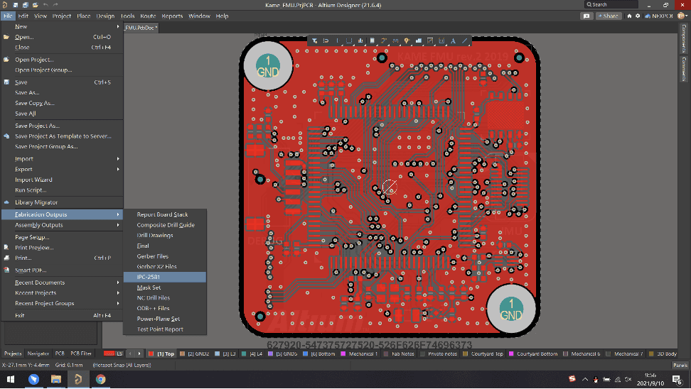
If a pop-up box for the file output destination shows up, select a folder to save the file in. Directly selecting the default location, (usually C:\Users\Public\Documents\Altium) is also done for the same function.
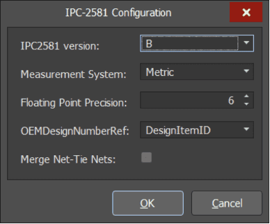
Confirm the version (A or B) of IPC2581, its units and decimal points from the configuration pop-up. Generally, you should select B, and leave the other settings as default. Then click OK to generate the output file.
Checking Output File
- Open the file explorer and navigate to the custom or default output folder based on which one you chose earlier. You should see a folder that’s named after your project (In my example below, the project name was Kame_FMU)
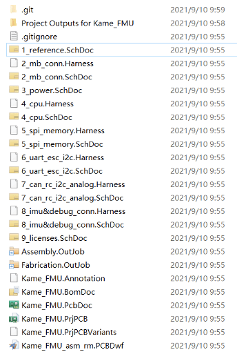


- Open the output folder for the project and you will see a unique output file titled XXX.CVG and an accompanying Status Report.txt. You should check Status Report.txt for error messages. I prefer using Visual Studio Code to open XML files, but even Notepad will do.

Checking CAD
Although the XML file can be well organized and read, it is not intuitive to read because the information such as copper layer and stacking is in image format. A CAD viewing software is used to check if there are any errors. Vu2581 is a free IPC-2581 viewer, and is one of the go-to software for viewing.
Vu2581 unique features include measuring distance between objects, setting colors and visibility for nets, pads, and layers; setting highlight colors for one or more components; and displaying information such as drill hole size and layer thickness.
Using Vu2581
Double-click Vu2581.exe to execute the file, click the Open icon, and select the XXX.CVG file from the folder we previously targeted.
If you get any error pop-ups, check and identify the causes carefully. Of course, errors can be caused by the software. In that case, check if you have missing layers, pads, etc.
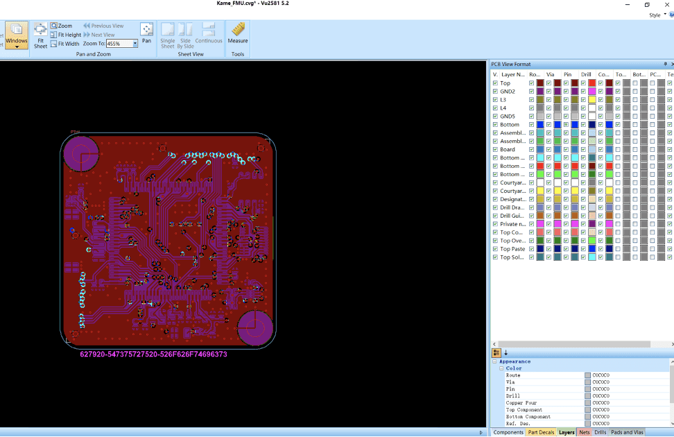
The tabs shown in the lower-left corner of the picture each have their different contents.
- Layers - used to display information about the layers. You can see how many layers are there, and select to check different layers, as well as choose to display different features such as pins, vias, and copper layers.
- Netlist - You can check whether it is displayed or not. Select one or more of these nets, which will be highlighted correspondingly on the diagram.
- Drills - Drilling information. You can check whether it is displayed. Drillings of the same specifications are categorized. This is similar to Gerber's drilling table.
- Pads and Vias - Information on pads and vias. You can check whether it is displayed or not.
- Components - BOM list, including bit number, name, assembly method, height, and other information.
- Part Decals - Device stickers, for some additional information on assembly.
